|
Introduction to Lens Design |
|
Technology -
Technology
|
Brandon Dube for opticallimits.com under exclusive license
Why’d they do that? Introduction to Lens Design for Photographers
To most photographers camera lenses are black boxes. You mount one to your camera, focus, maybe set the aperture, and take pictures. Some are brighter than others, some are sharper than others, some have more chromatic aberrations (and so on), but the internals remain a mystery. This article is the first in a series the goal of which is to provide a little background and context for lens design without getting too heavy into the mathematics involved.
Back to the beginning
Before we can even begin to think about something as complex as a zoom lens or even as seemingly simple 50mm f/1.8 prime lens we must take baby steps and look at what single lenses do. There are many types of singlets, rather than bore the reader with a description of all of them here is a diagram of many:
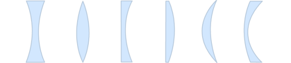 Figure 1. From left to right we have biconcave, biconvex, planoconcave, planoconvex, meniscus (positive), and meniscus (negative).
Each of these shapes bends light in a different way; readers may remember from high school that a biconcave lens will spread out or diverge light and a biconvex lens will focus or converge light. Each of these different lenses has a different “inherent” property such as the plano-convex or nearly plano-convex lens with greater curved surface facing away from the image plane generally minimizing spherical aberration but the specifics of these things are outside the scope of this article.
Before we can begin to design a lens for an application we must understand what a lens does and a little bit about how the lens is made. First and foremost, a piece of glass that is flat on both sides is not a lens – it is a window. Our first interaction with optics is usually the introduction of Snell’s law: nisin θi=ntsin θt. It soon becomes clear that the higher the angle of incidence, the more light is diverted by hitting a change in medium.
Imagine a single surface boundary between air and a material with a refractive index greater than air. If the light hits the surface at normal incidence it will travel on the opposite side of the boundary, without its path changing. This is why windows and other flat pieces of glass (e.g microscope slides) do not focus light.
Unfortunately we do not have freedom to rotate our subjects around our lenses and then integrate all of that light. If we cannot change the angle of incidence with the beam itself we must change it with the surface. This is done by adding curvature which increases the angle of incidence smoothly and bring light to a nice focus. The most naturally thought of and simplest to manufacture shape is a sphere, and so we get the classic spherical surfaces of most lenses. The greater the value of θi the sooner the light will reach a focus and thus we get a lens with a shorter focal length.
The refractive index component of snell’s law is both a blessing and a burden. Without going into details (that will come later) the shorter the focal length the smaller the radius of curvature. The shorter the radius of curvature (henceforth, R) the steeper the slope of the surface becomes, making it sensitive to manufacturing error and giving rise to strong aberrations in the image.
One of glass’ many properties is how much dispersion it causes. Dispersion is simply the change in refractive index with respect to the wavelength of light. Different colors have different wavelengths, the standard spectrum for visible light instruments samples only three points, the F, d, and C lines. The change in refractive index for the different colors results in them reaching different foci – this is known as axial or longitudinal chromatic aberration.
Figure 1. From left to right we have biconcave, biconvex, planoconcave, planoconvex, meniscus (positive), and meniscus (negative).
Each of these shapes bends light in a different way; readers may remember from high school that a biconcave lens will spread out or diverge light and a biconvex lens will focus or converge light. Each of these different lenses has a different “inherent” property such as the plano-convex or nearly plano-convex lens with greater curved surface facing away from the image plane generally minimizing spherical aberration but the specifics of these things are outside the scope of this article.
Before we can begin to design a lens for an application we must understand what a lens does and a little bit about how the lens is made. First and foremost, a piece of glass that is flat on both sides is not a lens – it is a window. Our first interaction with optics is usually the introduction of Snell’s law: nisin θi=ntsin θt. It soon becomes clear that the higher the angle of incidence, the more light is diverted by hitting a change in medium.
Imagine a single surface boundary between air and a material with a refractive index greater than air. If the light hits the surface at normal incidence it will travel on the opposite side of the boundary, without its path changing. This is why windows and other flat pieces of glass (e.g microscope slides) do not focus light.
Unfortunately we do not have freedom to rotate our subjects around our lenses and then integrate all of that light. If we cannot change the angle of incidence with the beam itself we must change it with the surface. This is done by adding curvature which increases the angle of incidence smoothly and bring light to a nice focus. The most naturally thought of and simplest to manufacture shape is a sphere, and so we get the classic spherical surfaces of most lenses. The greater the value of θi the sooner the light will reach a focus and thus we get a lens with a shorter focal length.
The refractive index component of snell’s law is both a blessing and a burden. Without going into details (that will come later) the shorter the focal length the smaller the radius of curvature. The shorter the radius of curvature (henceforth, R) the steeper the slope of the surface becomes, making it sensitive to manufacturing error and giving rise to strong aberrations in the image.
One of glass’ many properties is how much dispersion it causes. Dispersion is simply the change in refractive index with respect to the wavelength of light. Different colors have different wavelengths, the standard spectrum for visible light instruments samples only three points, the F, d, and C lines. The change in refractive index for the different colors results in them reaching different foci – this is known as axial or longitudinal chromatic aberration.
Designing a singlet
Let’s get a little into the maths (there won’t be much more for the rest of this series) and complete a singlet design. The formula for the effective focal length (for all intents and purposes this is focal length as photographers call it) of a lens is 1/Φ where Φ is the total optical power of a system. Optical power is a measure of how strongly a lens converges or diverges light. The formula for the optical power of a single thick lens is Φ = ϕ1+ϕ2-(t/n) ϕ1 ϕ2 where , ϕ1 is the power of the first surface, ϕ2 is the power of the second surface, t is the thickness of the lens and n is the refractive index of the lens. The power of a single surface is given by ϕ = 1/R (n'-n) where n is the left hand refractive index and n’ is the right hand refractive index – sign convention matters! The expanded equation for a singlet lens in air is:
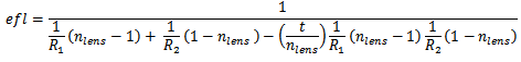 As you can see, there are many variables and thus ways to reach a solution. To keep the design simple for now we will use only one constrain, efl. The focal length of the lens should be a “standard” 100mm measured at the d line (yellow light).
Any lens must be made of a material, usually glass is chosen but sometimes acrylic plastics are used. At a later date materials will be explored in more detail, but Figure 2 is a sample set of common optical glasses to choose from and the index of refraction at all three of the standard visible wavelengths:
As you can see, there are many variables and thus ways to reach a solution. To keep the design simple for now we will use only one constrain, efl. The focal length of the lens should be a “standard” 100mm measured at the d line (yellow light).
Any lens must be made of a material, usually glass is chosen but sometimes acrylic plastics are used. At a later date materials will be explored in more detail, but Figure 2 is a sample set of common optical glasses to choose from and the index of refraction at all three of the standard visible wavelengths:
| Glass |
nd (yellow 587.56nm) |
nF (blue, 486.13nm) |
nC (red, 656.27nm) |
| N-FK5 | 1.48749 | 1.49227 | 1.48535 |
| N-BK7 | 1.51680 | 1.52238 | 1.51432 |
| N-SF2 | 1.64769 | 1.66125 | 1.64210 |
| N-LAF7 | 1.74950 | 1.76472 | 1.74320 |
Figure 2. Data from Schott Optical Glass Catalog, June 2014d
N-FK5 is an “ED” glass having extra-low dispersion. N-BK7 is the most common and cheapest optical glass. N-SF2 is a fairly common flint glass having high refractive index but high dispersion. N-LAF7 is an even higher index but still fairly common flint. This refractive index range is approximately all that is available to you as a lens designer, glasses exist up to just above Nd=1.8 but they are very expensive and cost inefficient. First instinct may be to reach for the ED glass, but it will force the use smaller radii of curvature to hit focal length constraints. This will cause a general increase in the aberration of the image from the lens.
For now do not be too worried about chromatic aberrations, but I recommend calculating the focal length at all three wavelengths and drawing that result to see how axial CAs come about yourself.
All of the different lens shapes from above should be considered in the design. Some have negative focal lengths due to the shape, so these may not be used. Any other shape is fair game. A later article will explore historical design forms such as the double-gauss, retrofocus, or sonar forms and touch base on why they are used, their pitfalls, and their strengths. The next article will cover aberrations in relative depth.
|
|